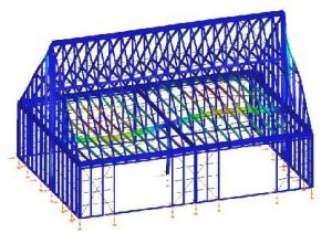
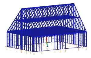
The house in Figure 5 shows a recently designed and executed structure in the town of Snagov.
The beneficiary’s express request was to draw up the project and build the house in as short a time as possible.
The main geometrical dimensions of the construction are: 9m wide, 12.5m long, 3m floor height and total height to the ridge of 7.95m.
The structure was designed for the climatic and seismic loads corresponding to the Snagov area, considering a useful load of 2 kN/m2 on the attic floor.
The architectural particularity imposed a ground floor with very few structural elements, for which a transverse and longitudinal supporting frame of laminated profiles was introduced.
The structure was made of C150x2.0 profiles for the wall uprights, with local reinforcements at the corners and at the edges of the gaps, and for the floor beams, C200x2.5 profiles arranged at 600 mm center distance were dimensioned. In the end, 8.5 tons of metal fabrication resulted, of which 1.3 tons represent the transverse and longitudinal support frame.
The project was completed in 7 days and the construction of the structure itself took about 10 days.
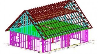
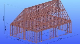
Figure 5 – Structural calculation model vs. the project made with light profiles
The 3D calculation model of the structure was made in the Consteel analysis and structural calculation program, considering simplified 3 pendulum stabilization links on the height of the wall uprights, intended to model the effect of the external and internal borders.
The floor beams were modeled in the same way, considering 3 stabilizing pendulum connections per opening.
The roof beams as rafters were provided between the supports secured by the links provided with one pendulum stabilization link each.
The corners of the structure, both in the wall and in the roof, were braced with steel strips, being defined as elements that can only take tension.
Although the number of links in such a structure in reality is much higher, the structural assembly in Figure 5 presented a very good response to the global stability analysis: the first element that loses its stability in the structure is the central pillar made of laminated profile HEA140, the critical load multiplication factor from the dangerous combination (permanent loads+useful floor) resulting being αcr=6.86 (Figure 6a).
The buckling sensitivity analysis highlights the elements sensitive to the loss of global stability those with fewer connections (the rafters, which were very rarely fixed).
The results of the global checks, according to the Eurocode calculation methodology, indicated a degree of use of the elements of a maximum of 88%, these being generally the edging profiles of the gaps, which accumulated a higher load due to the lack of uprights on the surface of the gaps.
a) αcr=6.86 b). Tfloor=4.66 Hz
Figure 6: The result of the stability analysis and that of the dynamic analysis
It is interesting to note that the strength checks indicate that C150x2.5 profiles are also suitable for the floor beams, but in the dynamic analysis vertical vibration appears at a frequency below 5 Hz (Figure 6b), which can generate undesirable effects in operation in the combination loads 1.35 x permanent + 1.5 x useful.
The results of the dynamic analysis using C200x2.5 profiles show that the same vibration form occurs at a frequency of 5.56 Hz, which is still very close to the recommended critical threshold of 5 Hz.
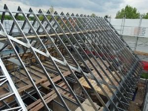
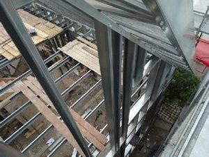
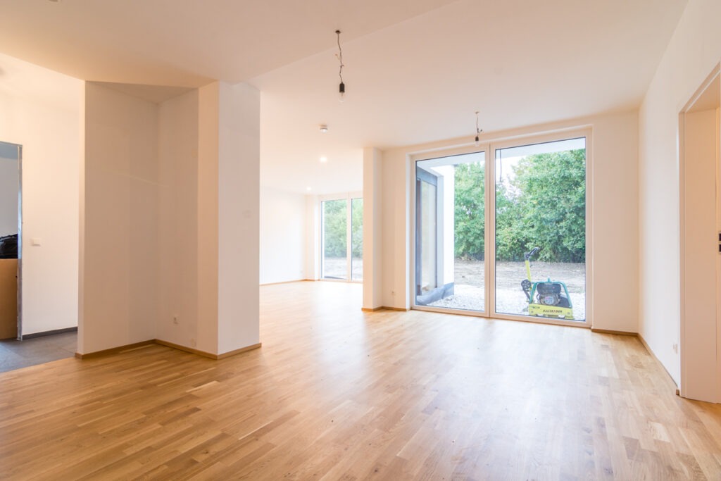
Figure 7: The structure of the analyzed house in the execution stage
Discussions regarding the results of numerical analyzes and their comparison with abacus
Having the detailed results of the numerical analyses, using automated tools, it is very easy to make a comparison, regarding the accuracy with which we can configure a house on a metal structure, using the abacus provided by [14] (see Figure 8).
Considering the maximum axial force resulting from the calculation NEd=60kN, the level height of 3 m and the maximum eccentricity h/6, we find the C150x2.0 profile used in the analysis for the wall uprights.
Proceeding in a similar way for the floor beams, considering as input data the opening of the element of 4.5 m, the distance between the rules of 600 mm and the useful load of 2 kN/m 2, we find that the C150 profiles have a limit of use of 3.54 m.
Regarding the selection of C200x2.00 profiles, they are at the limit of use of 4.44m (probably C200x2.50 falls within the acceptable range, but is not covered by the table), the safest choice being the C250x2.0 profile or profiles Σ200×2.00.
The tables in reference [14] do not provide us with assistance in the choice of profiles for the construction of the roof, the choices in this situation being possible to be guided by the resistances to bending moment, shear force and local effects from the concentrated force on the support.
Without an optimization of these choices, according to the performed calculations, a robust structure results, with strength reserves at the level of structural elements, but special attention must be paid to the joint details, where the information from reference [3] can be of great help.
On the other hand, by focusing our attention only on the resistance and stability criteria, using a powerful calculation program, the aspects regarding the vibration of the floor for an inexperienced user may escape, which could lead to undesirable side effects in operation.
In conclusion regarding the aspects of the design process, we can state that the design of the structure of the houses on a light metal structure reserves traps for the inexperienced, but the calculation abacus behind which there is a thorough research, can offer us quick solutions, even if some elements will be oversized with considerable endurance reserves.
The problems related to the bracing of the structures still remain nerve points, where standardized and tried solutions can represent the accessible way adopted in the designed solutions.
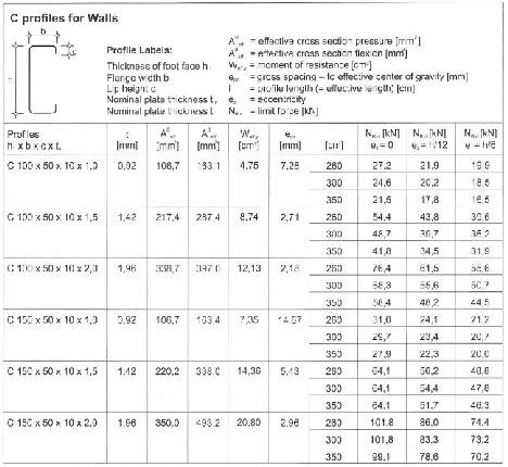
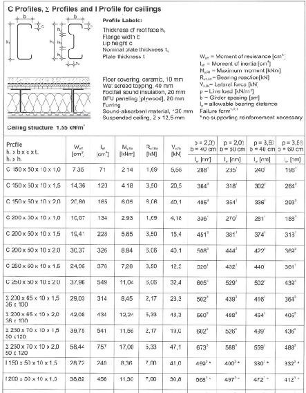
Figure 8: Selection table for wall studs and floor joists
ConCluSIonS
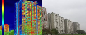
This paper analyzes myths and truths regarding energy efficiency and some aspects regarding the design of light metal frame houses.
The authors of the article, through an example made by a house on a light metal structure, demonstrate that they can be designed in such a way as to result in a very low energy consumption, even in very cold climates.
By using perforated profiles with increased energy efficiency or adequate thermal insulation solutions and details, houses can be obtained, the energy consumption of which can be reduced to 50% compared to the energy requirement of conventional buildings, these being classified in energy consumption class A. Regarding the design, modeling, analysis and calculation of metal house structures in general, it remains a complex problem, due to the phenomena derived from the slenderness of the walls of the sections.
The local instabilities of the profile walls (local warping or distortion of the section) through the interaction with the loss of the general stability of the structural element, which may have local cutouts, or may be perforated for reasons of energy efficiency, generate situations that complicate the analysis of the behavior of the structures at the global level, but also at the constituent element level, for which instability is the main dimensioning criterion.
Prescriptive methods can be an alternative for simplifying the design process, in the case of some structures, whose architecture is covered by the typical solutions in the normative documents currently available.
An application was presented that treats the 3D structural model as a whole during the whole analysis process, considering all the links of the structural elements as they were modeled by the user, performing the checks of the structural elements by considering the effective section.
Even if the analysis process is automated, the design of the structure of houses on light metal structure reserves pitfalls for the inexperienced. The problems related to the bracing of structures still remain nerve points, for which laboratory tests and advanced calculation methods offer immediate solutions.
Authors of the document
Zsolt Nagy – Lecturer, Cluj Technical University, Faculty of Construction, Department of Structures
Cristina Câmpian – Professor, Cluj Technical University, Faculty of Construction, Department of Structures
Paul Perneș – Assistant, Cluj Technical University, Faculty of Construction, Department of Structures
reference
[1] Case Study: Constantin’s Family House, Ploiesti, Romania, Access Steel information portal, SP024a-EN-EU, 2004.
[2] Dubina, D., Fulop, L., Aldea, A., Demeteriu, S., Nagy, Zs., Seismic performance of Cold-formed Steel Framed Houses, Proceedings 5 th International Conference on Behavior of Steel Structures in seismic areas – STESSA 2006, 14-17 August 2006, Yokohama, Japan, Taylor&Francis / Balkema, London, 2006, (Eds. F.M. Mazzolani, A. Wada), pp. 429-435
[3] Prescriptive Method for Residential Cold-Formed Steel Framing, AISI, 2000.
[4] Standard for Cold-Formed Steel Framing – General Provision (2007), AISI S200-07, American Iron and Steel Institute
[5] Standard for Cold-Formed Steel Framing – Product Data (2007), AISI S201-07, American Iron and Steel Institute
[6] Standard for Cold-Formed Steel Framing – Floor and Roof System Designs (2007), AISI S210-07, American Iron and Steel Institute
[7] Standard for Cold-Formed Steel Framing – Wall Stud Design (2007), AISI S211-07, American Iron and Steel Institute
[8] Standard for Cold-Formed Steel Framing – Header Design (2007), AISI S212-07, American Iron and Steel Institute
[9] Standard for Cold-Formed Steel Framing – Lateral Design (2007), AISI S213-07, American Iron and Steel Institute
[10] Standard for Cold-Formed Steel Framing – Truss Design (2007), AISI S214-07, American Iron and Steel Institute
[11] Standard for Cold-Formed Steel Framing – Code of Standard Practice (2005), American Iron and Steel Institute
[12] Standard for Cold-Formed Steel Framing – Prescriptive Method for One and Two Family Dwellings (2007), AISI S230-07 American Iron and Steel Institute, Washington, D.C.
[13] Cold-Formed Steel Framing Design Guide, D110-07, (2007), American Iron and Steel Institute, Washington, D.C.
[14] European Lightweight Steel framed Construction, Published by Arcelor, printed by Victor Buck, 2005, ISBN 2-9523318-2-0
[15] WP 6 – Guidance for architects and engineers on energy efficient solutions in steel: Design guidance on energy and thermal improvements for residential buildings, RFSR- CT- 2008-00038, University of Aachen
[16] Knowledge in the use of steel-intensive dry construction systems in housing, Research Fund for Coal and Steel – Final report, 2004
[17] SR EN 1993-1-3, Eurocode 3: Design of steel structures Part 1-3: General rules
[[17] SR EN 1993-1-3, Eurocode 3: Design of steel structures Part 1-3: General rules Additional rules for structural elements and cold-formed sheets, ASRO, 2007
[18] SR EN 1993-1-5, Eurocode 3: Design of steel structures. Part 1-5: Structural members of flat plates required in their plan, ASRO, 2007.
[19] www.consteelsoftware.com